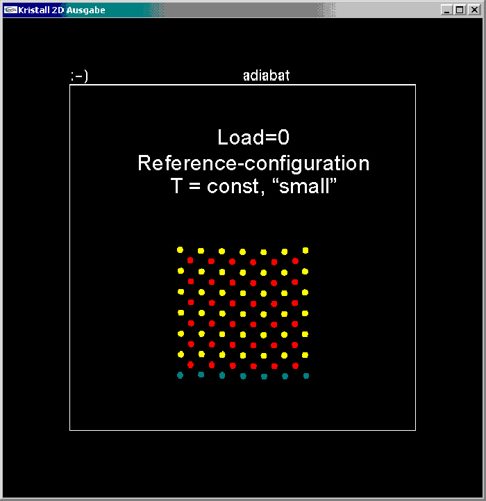
Screenshot 1 : 85 particle body at initial configuration.
-> Back to previous page
-> To table of contents
-> Jump to animation links
In this simulation again 85 atoms of type "yellow" and "red" are initially placed in a square (austenitic) lattice as shown in screenshot 1.

Screenshot 1 : 85 particle body at initial configuration.
The process is performed at a low and constant temperature level. Thus the Lennard-Jones parameters are chosen such as to provide a stable austenitic lattice even at low temperatures. Therefore this experiment investigates the mechanic properties of the body, rather than its thermodynamics.
We will apply an increasing load in the horizontal direction to the uppermost row of atoms and record the displacement of this row from its initial position as calculated by the dynamic simulation algorithm. Screenshot 2 illustrates this setup:
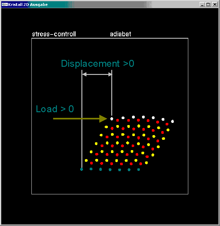
Screenshot 2 : Setup of the load-controlled experiment. Positive Loading.
The load increases up to a maximum, and this increase is followed by unloading. After the zero load is passed, the process is repeated for a load in the opposite direction as shown in screenshot 3:
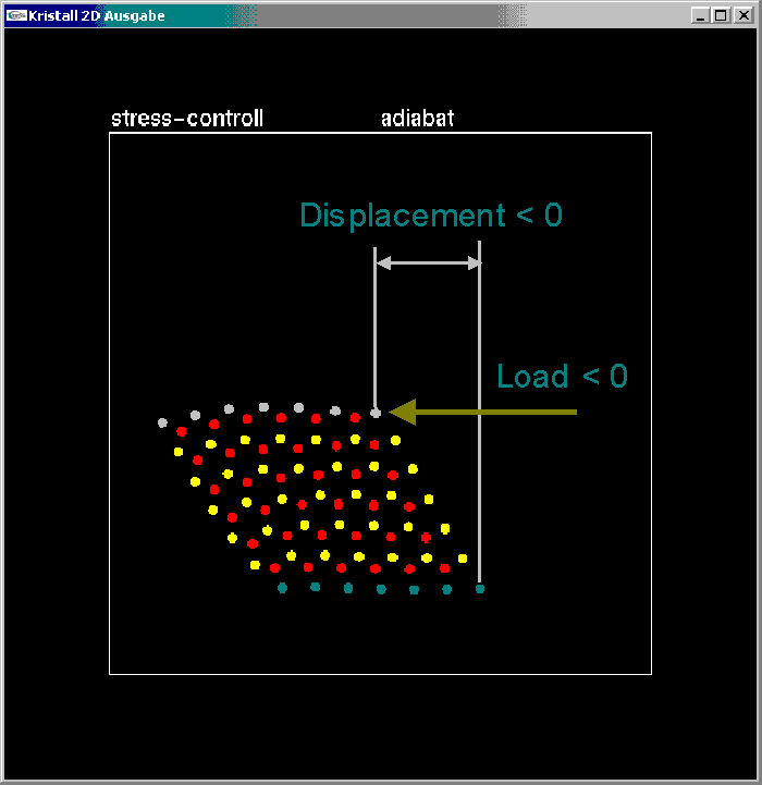
Screenshot 3 : Opposite shearing under negative loading.
The applied loads may be plotted versus the calculated displacements so as to give the following load-displacement-plot:
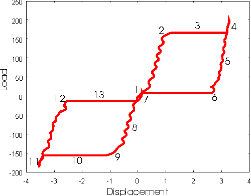
Discussion of the load-displacement-plot:
| 1: | Initially the block exists in the rectangluar, austenitic lattice. In this configuration, the uppermost row has zero displacement. The loading starts. |
| 1 -> 2: | With increasing load the block is sheared elastically. The load-displacement curve shows a nearly linear progress, superposed by small oscillations of the block as such. If we idealize this part of the curve as a straight line, its slope provides the Young modulus of the austenite. |
| 2: | At a certain critical load -- the yield load -- the phase transition occurs. |
| 3: | While the phase transition occurs, the load remains constant. The crystal lattice is sheared into the martensitic configuration. A large displacement at the yield load is observable; this horizontal part of the load-displacement-plot is called the yield line. In order to keep the temperature constant we must cool. |
| 4: | At the end of the yield-line the load increases again. The displacement is proportional to the load. Thus a second linearly-elastic line is found, whose slope provides the Young modulus of the martensite. Afterwards the load is reduced. |
| 5: | While unloading, the body stays on the second elastic line even although the load is lowered below the yield load. |
| 6: | A second critical positive load is reached, the recovery load. |
| 6 -> 7: | At constant recovery load (still positive), the displacement is recovered: Under this load, we observe a shearing motion of the martensite back into the austenite. This process is dynamic and we must cool so as to prevent the lattice to break through to the left. A significant, large hysteresis has occured during the loading/unloading process. |
| 7: | The body is in the austenitic configuration again, slightly sheared. Thus this point is located on the austenitic elastic line. Further unloading to zero load leads back to the original shape. |
Afterwards the body may be loaded in the opposite direction, and a symmetric load-displacement plot is shown: Linearly-elastic loading of the austenite (8), the occurrence of a critical yield load (9), the large displacement along the yield-line (10) and the linearly-elastic shear of the martensite (11). Upon unloading: Unloading along the martensitic elastic line (11-12), the occurrance of the recovery load (12), the recovery line into the austenitc state (13).
| You may view gif animations of this simulation: |
| Go to animation page: Full circle! (1.28 Mb) |
| Go to animation page: Half circle! (644 Kb) |
Thermodynamics states that at temperature T and under load P a configuration is stable, which enables the body to adopt the minimal free enthalpy G(T,P) (Gibbs free energy):

Thus, for T negligibly small it is the enthalpy H(T,D, P=const) that has to be considered. This quantity is plotted below as a function of the displacement. It is calculated as the sum of the potential energy Epot and the product of displacement D and load P. The former was recorded during the dynamic simulation of the load-controlled process.
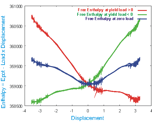
The dark blue curve represents the enthalpy at zero load, thus it is identical with the "measured" potential energy Epot. We find the minimum at zero displacement and thus the austenite is stable in the absence of a load. When the body is loaded with a load P=const, a straight line with the slope (-P) must be added to Epot. This straight line shifts the Epot-curve so as to create a second relative minimum. At the critical loads (yield or recovery loads) the energy barrier between the two minima vanishes, and the second minimum becomes an absolute minimum.
In the above plot, both situations are shown: The red curve represents H at the yield load. the minimum of that curve occurs at the displacement D=3, and thus the body is stable in the configuration that enables this displacement: It is the martensite. Once the body is in the martensitic configuration, it will stay there, even when the load is lower than the yield load. The reason for this behaviour is the fact that the body has a very small thermal activation. Although there may be energetically more favourable configurations, the body remains in the potential well of the martensite, because an energy barrier prevents it from transforming. It is only when the energy barrier vanishes, that the martensite may flip into another configuration, see the green curve.
It is interesting to understand the influence of the temperature for processes at a higher temperature level. For this purpose one has to calculate the entropy S as function of temperature and displacement at a consatant load. Once the entropy is calculated, the free enthalpy G(T,D,P=const) is the quantity, that has to be minimal in equilibrium. This analysis is still in progress.
-> Top
-> Back to previous page